Introduction
The topic of instrumentation has now reached such a level as to have become a subject in its own right. This chapter covers some of the basic principles of the science, with examples as to how it relates to automobile systems.
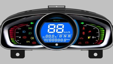
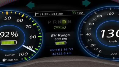
By definition, an instrumentation system can be said to convert a ‘variable’, into a readable or usable display. For example, a fuel level instrument system will display, often by an analogue gauge, a representation of the fuel in the tank.
instrumentation is not always associated with a gauge or a read-out type display. In many cases, the whole system can be used just to operate a warning light. However, the system must still work to certain standards, for example, if a low outside temperature warning light did not illuminate at the correct time, a dangerous situation could develop.
This chapter will cover vehicle instrumentation systems in use and examine in more detail the issues involved in choosing or designing an instrumentation system. contains many details associated with sensors, an integral part of an instrumentation system, and it may be appropriate to refer back for some information related.
Sensors
In order to put some limits on the size of this section, only electrical sensors associated with vehicle use will be considered. Sensors are used in vehicle applications for many purposes; for example, the coolant temperature thermistor is used to provide data to the engine management system as well as to the driver via a display. For the purpose of providing information to the driver, Table 13.1 gives a list of measured (things that are measured) together with typical sensors, which is representative of today’s vehicles.
Thermal-type gauges are used with a variable resistor and float in a fuel tank or with a thermistor in the engine water jacket. shows the circuit of these two together. The resistance of the fuel tank sender can be made non-linear to counteract any non-linear response of the gauge. The sender resistance is at a maximum when the tank is empty. A constant voltage supply is required to prevent changes in the vehicle system voltage affecting the reading.
Air-cored gauges
Air-cored gauges work on the same principle as a compass needle lining up with a magnetic field. The needle of the display is attached to a very small permanent magnet. Three coils of wire are used and each produces a magnetic field. The magnet will line up with the resultant of the three fields.
The current flowing and the number of turns (ampere-turns) determines the strength of the magnetic flux produced by each coil. As the number of turns remains constant the current is the key factor.
Motor, which is driven by the output of a divider and a power amplifier. The divider is to calibrate the action of the stepper motor to the distance covered. The actual speedometer gauge can be calibrated to any vehicle by changing the time delay of the constable.
Last word
A system for driving a tachometer is similar to the speedometer system. Pulses from the ignition primary circuit are often used to drive this gauge. Shows the block diagram of a typical system.
Starmusiq offers a vast collection of high-quality music to cater to every listener’s taste. With its user-friendly interface and easy navigation, finding and downloading your favorite songs has never been easier. Whether you’re a fan of Bollywood, Hollywood, or regional music, Starmusiq has got you covered.