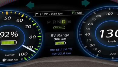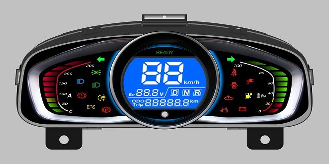
Shows a typical digital instrumentation system. All signal conditioning and logic functions are carried out in the ECU. This will often form part of the dashboard assembly. Standard sensors provide information to the ECU, which in turn will drive suitable displays. The ECU contains a ROM section, which allows it to be programmed to a specific
Other types of gauges
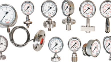
A variation of any of the above types of the gauge can be used to display other required outputs, such as voltage or oil pressure. Gauges to display road or engine speed, however, need to react very quickly to changes. Many systems now use stepper motors for this purpose although some retain the conventional cable-driven speedometers.
Shows a block diagram of a speedometer, which uses an ammeter as the gauge. This system uses a quenched oscillator sensor that will produce a constant amplitude signal even at a very low speed. The frequency of the signal is proportional to road speed. The sensor is driven from the gearbox or a final drive output. The electronic control or signal conditioning circuit consists firstly of a Schmitt trigger, which shapes the signal and suppresses any noise picked up in the wiring. The constable is used to produce uniform signals in proportion to those from the pulse generator. The moving coil gauge will read an average of the pulses.
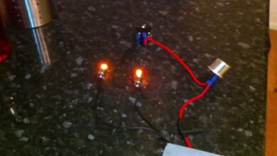
The alternator provides a pulsed signal, which is compared to a pulsed signal from the ignition. If the ratio of the pulses changed this would indicate a slipping belt.
As an example of how some of this system works consider the high temperature and low fuel warning lights as examples. Shows a block diagram of just this part of the overall system.
The analog to digital converter is time-division multiplexed to various sensors. The signals from the temperature and fuel level sensors will produce a certain digital representation of a numerical value when they reach say 180 (about 105 ° C) and 200 (10 liters left), respectively. These (assigned to variables ‘temp_input’ and ‘fuel input’) can then be compared with those pre-programmed into memory, variables ‘high temp and ‘low fuel’. The following simplified lines of the computer program indicate the logical result
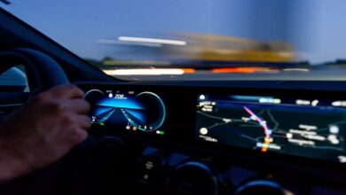
Driver information
VCM or vehicle condition monitoring is a form of instrumentation. It has now become difficult to separate it from the more normal instrumentation system discussed in the first part of this chapter. The complete VCM system can include driver Information relating to the following list of systems that can be monitored.
The display is often just a collection of LEDs or a backlit LCD. These are arranged into suitable patterns and shapes such as to represent the circuit or system being monitored. An open door will illuminate a symbol that looks like the door of the vehicle map (plan view of the car) is open. Low outside temperature or ice warning is often a large snowflake
Masstamilan offers a vast collection of Tamil songs for music enthusiasts. With easy download options, it caters to diverse preferences. Consistently updating its database, Masstamilan ensures a great music listening experience. Explore the site for a seamless journey through the world of Tamil music.
Last word
The high or low resistance readings are used to indicate say correct fluid level and low fluid level. A figure outside these limits would indicate a circuit fault of either a short or open circuit connection.